T 4.31 Failure or malfunction of a network component
A failure or malfunction of active network components impairs the availability of the entire network or sections of it. Three different situations can be distinguished:
- With a failure or malfunction of the entire network component, the network is rendered inaccessible for all stations connected to it. With such a failure or malfunction of just a single port, only the station connected via this port is no longer able to access the network.
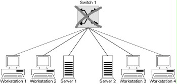
Example: A failure of the central switch 1 as shown in the diagram below results in a complete breakdown of communications between the connected stations.

Figure: Failure of a central switch
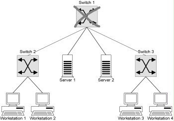
- Another situation involves active network components which are not connected directly to the network segments of mutually communicating workstation and server systems, but which are located in the signal path between these systems. If no redundant signal paths are present between the workstation and server systems in question, a failure or malfunction of one or more such components might fully or partially disrupt communications between these systems.
Example: If switch 1 fails as shown in the diagram below, then workstations 3 and 4 can no longer communicate with the two servers or the remaining workstations.

Figure: Failure of a switch
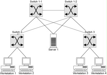
- The last situation involves active network components which are not necessarily located in the signal path between the workstation and server systems, due to the existence of a second, redundant signal path. Some of these active network components might have been installed for the purpose of redundancy or load balancing. With a failure or malfunction of one or more of these components, communication between the workstation and server systems is still possible, but the available bandwidth in the network is restricted, because redundant signal paths might no longer be available or load balancing in the network might be impaired.
Example: Failure of one of the redundant switches 1-1 or 1-2 as shown in the diagram below can restrict the available bandwidth for communications between the workstations and the server.

Figure: Failure of a redundant switch
The MTBFs (Mean Time Between Failure) quoted by the manufacturers of the components can be used to estimate the risk of failure.
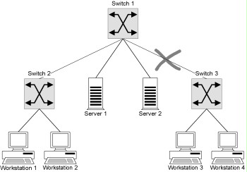
In the case of hubs, there are basically two different techniques of establishing connections between individual modules, and therefore between the segments connected. As regards products with a passive backplane - the element which establishes connections between modules - these backplanes provide only the electrical connections between the modules. The control unit as such is integrated in the individual modules. In the case of products with an active backplane, this element provides additional functions such as configurable communications between the modules, signal amplification etc. In general, active network components with an active backplane are more susceptible to malfunctions than active network components with a passive backplane. The failure of an active backplane leads to a complete breakdown of communications within the affected network component. In contrast, passive backplanes are designed in such a way that only mechanical violence or force majeure (e.g. lightning) can damage them. In many cases, component faults can be attributed to the related power supply units, as the components require a stable power supply. For this reason, many components are delivered with redundant power supply units or can be refitted with them. The failure of a passive network component can impair the availability of a network to the same extent. This applies, for example, to cables and connectors which link segments together. Such a threat can arise as a result of improper cable installation (e.g. non-observance of the maximum bending radius), incorrect installation of connectors (particularly in the case of optic fibres) and interference due to electromagnetic incompatibility.
Example: If a damaged cable or connector disrupts the link between switches 3 and 1 as shown in the diagram below, workstations 3 and 4 are still able to communicate with each other, but no longer with the servers or workstations 1 and 2. The communication between workstations 3 and 4 will still be possible.

Figure: Failure of a switch

