
S 1.39 Prevention of transient currents on shielding
Initiation responsibility: Head of IT
Implementation responsibility: Building Services
The standards for IT infrastructures (DIN EN 50173, DIN EN 50174-2 "Cabling installation") describe the shielded and unshielded data cabling as well as the grounding and shielding requirements for these systems. When shielded data lines are used, the standards differentiate between areas used for technology (e.g. server rooms and computer centres) and areas used for general IT purposes. In areas used for technology, the standards specify that the shielding must be connected at both ends and that the system and components must be tightly intermeshed. In areas generally used for IT infrastructure such as the cables on a floor in a building, the standards specify that the shielding must be connected at one side. Connecting both ends of the shielding is optional.
If network operations are disrupted due to transient currents, then the cause of their formation should be analysed first. Since the frequencies used in IT transmission methods are constantly increasing, the systems become more sensitive to high-frequency interference. In addition, the systems themselves can also become emitters of high-frequency interference under some circumstances and disrupt neighbouring equipment and systems. If operational disruptions are detected, then the proper solution must be worked out depending on the local conditions. Since a lot of specialised knowledge is required to do this, it is generally recommended to contract a specialised company to evaluate and analyse the situation and work out a solution.
There are various ways of preventing transient currents on, for example, the shielding of data lines:
Transient currents can be avoided in the TN-C network by only using shielded data lines to link those IT devices connected to a common electrical distribution system. This must be checked and ensured each time the data network is expanded.
Connecting data line shielding at one end only is often suggested as a measure for preventing transient currents in TN-C and TN-CS networks. This method is actually effective in terms of transient currents, but it should only be used when absolutely necessary and as a exception to the rule for the following reasons:
- Shielded cables whose shielding is only connected at one end are much more strongly affected by radiated interference. At the same time, they radiate higher levels of interference than unshielded balanced lines. It must therefore be assumed that there will be more interference in the data transmission (e.g. in terms of availability or integrity) in cables where only one end of the shielding is connected than in all other cables.
The higher level of emission of exploitable signals from lines connected in this manner represents a security risk in terms of the confidentiality of the information transmitted. - Even when all technical disadvantages of connecting only one end of the shielding are deemed acceptable, the problem of consistent implementation remains. Thorough inspections of all work performed on the data network must be carried out to ensure that the shields of those cables where the shield is only connected at one end are not inadvertently connected at both ends. It is very difficult and time-consuming to find these types of connections later on.
In terms of safety, it is best to design the power distribution network in the entire building as a TN-S network. In this case, the PE and N conductors are routed separately after the potential equalisation bar (PEB). It is generally no longer necessary to take individual measures on IT devices in this case. However, the information in S 1.28 Local uninterruptible power supply about the formation of a new TN-S network for the connected devices should be observed.
To ensure and maintain the effectiveness of the TN-S network design, it must be ensured that the only connection between the PE and N conductors in the entire network is on the PEB (ground). In actual practice, though, accidental creation of another connection between the PE and N conductors when a new device is connected or when working on the network cables cannot be ruled out. For this reason, changes to the data network should always be coordinated with Building Services. Furthermore, a TN-S network should be checked at regular intervals for proper grounding. This can be done whenever performing the inspections of the power supply grid which are required anyway and when problems are suspected (for example if intermittent disruptions in the data network occur over a longer period of time). As a minimum measure, a TN-S network in the low-voltage main distribution (LVMDP) should be equipped with a permanent differential current monitor on the three phases and the neutral conductor and another permanent current monitor on the central earthing point (CEP). All other technical safeguards serving for quality assurance of the TN-S network are explained in S 1.74 EMC-compliant power supply.
The following diagrams show how transient currents can form on shielding as well as possible countermeasures:
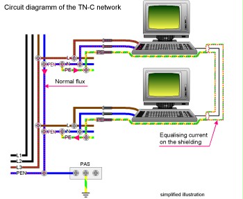
Figure 1: Formation of transient currents on shielding and possible countermeasures for a TN-C network
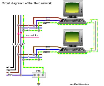
Figure 2: Formation of transient currents on shielding and possible countermeasures for a TN-C network
Review questions:
- Is the type of network for power supply of the IT components chosen in such a way that disruptions due to transient currents on the shielding of data lines are prevented?
- Use of the network type TN-C or TN-CS: Are precautions taken for protection of the IT components against external irradiation, emission from the line, and detection of transient currents?
- Has it been ensured by specialised knowledge and monitoring that the chosen type of network is also maintained in case of changes to the power supply grid?