
S 1.74 EMC-compliant power supply
Initiation responsibility: Head of IT
Implementation responsibility: Building Services
An EMC-compliant power supply is absolutely indispensable for problem-free functioning of modern IT systems as well as of support system required for their operation (from UPS to EPS to air conditioning technology). This topic is so complex that it cannot be included in a comprehensive description of an IT-Grundschutz safeguard; however, this is to show the basic principles whose realisation is necessary for the success of any subsequent measures.
TN-S system and central earthing point
Since October 2010, the standard DIN VDE 0100-444 "Low-voltage electrical installations - Part 4-444: Protection for safety - Protection against voltage disturbances and electromagnetic disturbances" in part 444.4.3.1 includes the following statement on TN-C systems:
"TN-C systems must not be used in newly created buildings that contain or presumably will contain a considerable amount of IT equipment. It is recommended to not continue using TN-C systems in existing buildings if this building contains or presumably will contain a considerable amount of IT equipment."
Regarding the TN-S systems, parts 444.4.3.2 states as follows:
"Systems in newly created buildings must be designed as TN-S system from feeding. In existing buildings that contain or presumably will contain important IT equipment and that are supplied via a public low-voltage network, a TN-S system should be created from the beginning of the installation system."
The VDE thereby takes account of the fact that, being the minimum requirement for proper operation of IT systems, the power supply network must be designed as TN-S system. Furthermore, the guideline VDI 3551 "Electromagnetic compatibility (EMC) in building services" of 01-2011 bindingly supports the requirements of a TN-S system with automatic monitoring.
The major difference between the two designs TN-C and TN-S is that the TN-S system only has one point where the neutral conductor and PE conductor are connected to each other. This point is the central earthing point (CEP).
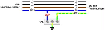
In a TN-S system the whole installation is designed as a 5-wire system starting at the CEP (the three phases as well as N and PE separated); that why it is also called "5-conductor network".
The location of the CEP is as close as possible to the feeding. It is not only the functional core part of a TN-S system. It also represents a first and easy-to-use measuring point for the quality of the TN-S system, i.e. for EMC compliance of the power supply. As the whole PE system of the power supply is a dead-end system when viewed from the CEP, i.e. there is no further connection to another conductor system (particularly not to the neutral conductor), pure physics prevents current from flowing via the CEP.
Note: In Switzerland, some responsible-minded power utility companies start to realise the CEP in their own sphere of responsibility, i.e. directly at the distribution board from where the final consumer is supplied. This way, the CEP is not necessary at the final consumer.
Unfortunately, modern electronic devices (this means almost all IT devices) have mains adapters effecting a more or less high current on the PE system - the so-called leakage current. According to the current standard drafts, this leakage current must not exceed approx. 0.2 per mille of the load current. This means that a leakage current of max. 0.2 mA is allowed per 1 A of load current. This current inevitably also passes the CEP and can be measured there. As the leakage current and the load current have a limited ratio, the comparison of the actual values of load current and leakage current allows for verification of proper operation of the TN-S system.
If the current on the CEP is too high, this may have several reasons. The two main reasons include defects in the devices or the fact that there is another, forbidden connection between the PE conductor and the neutral conductor in the system besides the CEP. In the first case, the defective device must be replaced. In the second case, the additional PE-N connection (also called earthing) must be removed.
Measuring point, measurability
Measuring the current on the CEP alone is not everything that can and must be done for proper operation of a TN-S system. The network, and here mainly the distributions, must be designed mechanically (i.e. with sufficient space) so that the following measurements can be performed at least with the feed lines of the distributions by using a current clamp:
- current on the CEP (this should be easily allocatable thanks to the corresponding labelling of its installation location),
- current of each individual conductor (L1, L2, L3, N, PE),
- current of all three phases together (L1 & L2 & L3),
- current on the three phases and the neutral conductor (L1 & L2 & L3 & N).
Professionals may use these measurements to obtain further important knowledge on the operating condition of the TN-S system.
However, such measuring using a current clamp only shows a snap-shot of the actual situation; this can be valuable, but does not allow for a final statement on the EMC compliance of the power supply. This requires further actions.
Network analysis
A really authoritative statement on the events in the power supply is only possible by means of permanent network monitoring and network analysis. Here, the following values must be measured in real time as important nodes of power supply and recorded for later evaluation:
- currents, voltages and frequencies of all 5 conductors,
- active, reactive and apparent power,
- frequency level up to a value around 100 kHz.
Only such real-time recordings allow for identification of time periods and correspondingly for making statements on the causes of individual failures. It is certainly not sufficient to only determine the level of the harmonic up to 1 kHz as a sum graph over a certain time frame.
Separation distances on routes and in power distributors
Magnetic fields are one of the most important reasons for failures that affect the IT systems via the power supply. Magnetic fields can only be shielded with enormous efforts, i.e. in fact they cannot be shielded in practice. Distance is the only reasonable parameter in this regard. However, this is usually not given in power distributors and on cable routes. That is why particular attention is to be directed to prevent creation of such fields. Due to the high complexity of the topic, only a few, but essential remarks are given.
The distance between the three phases and the corresponding neutral conductor should always be as short as possible. This will be of relevance with cable routes, e.g. if the five conductors (L1, L2, L3, N, PE) are installed as individual conductors due to routing reasons.
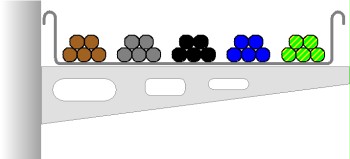
If this type of installation is used, the relatively high distances between the three phases (L1, L2, L3) and the neutral conductor will result in creation of large magnetic fields that couple both to the PE conductor and the cable support system, where they induce undesired currents.
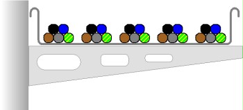
If the individual cores are installed as a 5-conductor bundle, i.e. each bundle includes L1, L2, L3, N and PE, then the magnetic fields will be significantly lower and the correspondingly induced currents and their negative effects will also be lower.
In power distributors it must be ensured that the neutral conductor is not routed on a separate path through the distributor, but is always installed as close as possible to the three phases. Such a narrow installation is the simplest and also most effective method to counteract the creation of electromagnetic fields.
However, in power distributors the PE conductor must and should be installed with considerable spatial separation from the four conductors L1, L2, L3, and N. This distance will highly reduce the magnetic coupling of currents to the PE conductor.
Additionally, it is also pointed out that the conductor distances stated in the lightning protection standard DIN EN 62305:2006-10 "Protection against lightning" must be observed when installing overvoltage arresters.
Furthermore, the separation distance as per DIN EN 50174-2 "Information technology - Cabling installation - Part 2: Installation planning and practices inside buildings" and as per standard VDE 0100-444:2010 "Low-voltage electrical installations - Part 4-444: Protection for safety - Protection against voltage disturbances and electromagnetic disturbances" must be observed. The requirements stated in these documents can rarely be met in practice. However, at least the distances as required by the standard must be implemented as far as possible.
Review questions:
- Is the current distribution network designed as TN-S system?
- Is the CEP clearly labelled in the plans and at its location?
- Is the CEP accessible for a measurement using a current clamp?
- Can the quality of the TN-S system only be assessed by reading the instantaneous values, or is there network analysis recording in real time?
- Are the recommended separation distances maintained as far as possible when designing and operating the power distribution network?