
S 2.277 Functional description of a switch
Initiation responsibility: Head of IT, IT Security Officer
Implementation responsibility: Administrator
Introduction
Initially, switches worked on OSI layer 2, but meanwhile switches with different functions are available. Manufacturers usually identify switches with the supported OSI layer. This resulted in the terms layer 2, layer 3, and layer 4 switch, with layer 3 and layer 4 switches actually being routers from a functional point of view. The initially different functions of switches and routers are combined on one device. This makes it more difficult to delimit the device types (switch or router). The essential differences between these devices are described in the introduction for module S 3.2 Routers and switches.
The first switches were based on the bridges that served for dividing large LAN segments into several small segments (collision domains) just like the state-of-the-art switches today. Bridges usually work using the store-and-forward technology. With this, every received Ethernet frame is read in and then the decision as to whether it is forwarded to another LAN segment is made based on the destination address. If data traffic is local, no forwarding takes place and the frame is only provided to the stations in the local network. This way, the local traffic is limited to individual segments, which may significantly reduce the network load if designed appropriately. For smaller segments, the share of collisions is also reduced and the performance enhanced. If a frame must be forwarded to another segment, it is stored to the cache of the bridge and then transferred to the destination port. Additionally, the integrity of a received frame may be checked with the help of CRC checksums during store-and-forward. Corrupt frames are discarded, which may contribute to further reduction of the network load.
Along with store-and-forward switching, switches are also equipped with the cut-through-forward switching mechanism where only the destination address is read - the first six bytes of a frame. This significantly reduces the delay between the receiving and the sending ports. However, it is not possible to filter out corrupt frames in the process. If faulty frames are forwarded unnecessarily, a bottleneck may be created as a result. An adaptive behaviour of the switch whereby the frame is checked during forwarding helps correct this. This does not filter out corrupt frames, but the switch is able to monitor the quality of the frames. If the percentage of corrupt frames exceeds a previously specified value, the switch switches this port to store-and-forward for future filtering.
The following figure illustrates a so-called switching table by way of example. This table contains information on the port the station with the corresponding MAC address is connected to. The switch learns this assignment dynamically. As opposed to a hub, the switch only sends an Ethernet frame to the port the destination computer is connected to.
As a consequence, the bandwidth available to a device is not affected adversely by the communication between other connected stations. Another effect is that the communication between two stations cannot be read by any of the other stations. This does not include broadcasts and multicasts sent to all connected stations. Likewise, frames with still unknown destination MAC addresses are forwarded to all ports.
| Destination MAC address | Destination switch port |
|---|---|
| 0001.02c4.fdca | Fast Ethernet0/4 |
| 0001.026d.d412 | Fast Ethernet0/8 |
| 0008.a345.12f3 | Fast Ethernet0/12 |
| 0060.97ac.de59 | Fast Ethernet0/16 |
| ... | ... |
Table: Switching table
A frame directed to the station with the MAC address 0001.02c4.fdca is only forwarded to port 01 by the switch.
Since the switching table is used for controlling the flow of data, it must be protected against manipulations. A couple of attacking methods endangering the integrity and availability of these tables are known (see T 5.112 Manipulation of ARP tables).
Layer 3 and layer 4 switches work analogously on a correspondingly higher OSI layer.
If a local network with a complex topography contains several switches, it may happen that there are several potential routes for the connection between two devices. However, switching only works if the port a packet must be forwarded to is known at any given point of time. Otherwise, there is the risk of loops being created in the network, on which packets are circulated and never reach their actual destination. Therefore, switches provide the option of automatically "negotiating" a logical network infrastructure with each other (a so-called Spanning Tree of the network) allowing for smooth functionality. To this end, the so-called Spanning Tree Protocol (STP, IEEE 802.1d) is used. Redundant connections in the network are disabled automatically and only re-enabled if the primary connection determined via STP is not available.
For this, a priority reference and an unambiguous MAC address must be assigned to every switch, there must be a multicast address for all switches, and every port must be clearly identifiable using an ID.
In order to limit the broadcast traffic in a "switched" network, virtual networks (VLANs) can be created. Here, a logical network structure is formed in a physical network by connecting workstations and servers with similar functions to form a virtual network. The reasons for consolidation into a VLAN may be based on organisational or technical reasons.
For example, in terms of corporate organisation it is possible to consolidate all employees of a department to a single network group, even if they are distributed to different floors. In terms of work organisation, employees working together on a project can be consolidated to a single network group, even if they belong to different departments.
Every VLAN forms a separate broadcast domain. A VLAN need not be limited to an individual switch, but it may cover an entire switched network. In this case, the network users no longer form a network segment due to their location, but can be consolidated to a group with other users within the intranet regardless of their location.
A differentiation between port- and host-based VLANs is made. For port-based VLANs, individual ports on a switch are directly assigned to a VLAN. This means that the assigned port is fixedly assigned to a certain VLAN regardless of the connected station. For host-based VLANs, the affiliation of a VLAN is controlled by the MAC address or IP address of the connection station, for example. For host-based VLANs, the user may connect his/her terminal device to any location inside the network without losing the affiliation to his/her VLAN.
The option of extending VLANs across several switches is referred to as trunking. Here a physical port is reserved per switch for the inter-switch communication; the logical connection between the switches is termed the trunk. Trunking is implemented with the help of different, sometimes proprietary trunking protocols. The Ethernet frame is encapsulated in the trunking protocol for the exchange of information between the switches. This way, the destination switch is able to allocate the information to the related VLAN. IEEE 802.1q and the proprietary protocols ISL (Inter Switch Link) and VTP (VLAN Trunking Protocol) from the manufacturer Cisco, for example, are used as the standards.
In some cases, the process of bundling (consolidating) several physical connections between switches in order to achieve correspondingly higher throughput rates is also referred to as trunking. This functionality is also referred to as "Channel Bonding" or "Channelling" on the other hand. If the term trunking is used in a document, you must therefore always pay attention to which sense the term is actually used in. In this document, trunking always refers to the option of distributing VLANs across several switches.
The following figure illustrates a configuration with two switches connected with the help of a trunk port. The computer also connected to a trunk port at the left-hand switch constitutes a potential security risk, since it has access to the data from all VLANs configured on the switch.
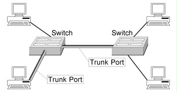
Figure: Trunking
If a VLAN covers several switches, the data traffic between these components is increased in practice by the share of information transmitted with the help of the trunking protocol. The communication between participants of different VLANs is performed using OSI layer 3, i.e. the packets are routed across the VLAN. Routing may be performed on a switch that supports routing functions (see also the section about layer 3 switches in the introduction for module S 3.2 Routers and switches) or on a connected router that connects the VLANs on the OSI layer 3.
The following figures show examples for a (port-based) VLAN covering three different floors of a building and for a configuration with two different VLANs on one switch.
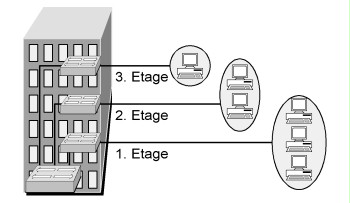
Figure: Example of a VLAN
Despite statements made by some manufacturers, it must be taken into consideration that VLANs were not developed in order to meet security requirements in the field of network separation. VLANs offer numerous points of attack so that additional safeguards must always be implemented, particularly in the field of separating networks worthy of protection. In the following exemplary figure, secure separation between VLAN 1 and VLAN 2 cannot be assumed, since the two VLANs are implemented on the same switch.
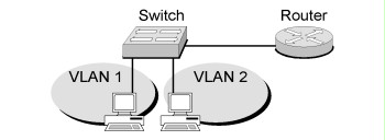
Figure: Two VLANs on the same switch
VLANs with different protection requirements should not be installed on the same switch. If this is nevertheless necessary for important reasons, additional safeguards must be taken in any case in order to guarantee an appropriate level of security. The network of a DMZ located between the internal network and the internet must in no case be configured as VLAN on the same switch as the internal network.
In the following figure, secure separation of two VLANs with different protection requirements was implemented by configuring only one VLAN per switch. The networks are connected by a router acting as packet filter.
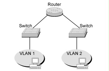
Figure: Secure separation of VLANs
Review questions:
- Are additional safeguards taken if internal VLANs with different protection requirements are configured on the same switch?
- Has it been ensured that the VLAN of a DMZ is not configured on the same switch as the internal network?