
S 2.278 Typical operational scenarios in which routers and switches are used
Initiation responsibility: IT Security Officer, Head of IT
Implementation responsibility: Administrator, Head of IT
The operational purpose of routers decisively determines the systems' configuration. Moreover, the use also determines the additional functions to be provided by a router.
Routers in the internal network
In many installations, routers are used as pure LAN-to-LAN routers in order to connect subnets and to prevent the side effects of purely "switched" networks, for example so-called broadcast storms. However, switches with integrated routing function are increasingly used for this function today (layer 3 or layer 4 switches, see also S 2.277 Functional description of a switch). For this operation scenario, the security requirements regarding the router strongly depend on the protection requirements of the subnets connected by the router.
Routers for connecting to external networks
If a router is used for connecting an organisation's own network to external networks, this router is referred to as a border router. Often, border routers are also integrated into a security gateway where they assume the function of the external packet filter (see below). For routers connected to third party networks, the security of the device is particularly important, since they are directly exposed to attacks from the outside.
Routers as packet filters
Routers are often used as a part of security gateways to establish a connection to public networks (for example the internet). In the following example, the security gateway consists of an internal packet filter, an external packet filter, and an application gateway. Instead of application gateways, stateful inspection systems are also often used as central parts of security gateways. The specified filter rules are configured both on the central system and on the routers (internally and externally). The set of rules is established by configuring access control lists (ACLs) on the routers.
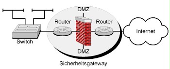
Figure 1: Routers as packet filters
The packet filtering function is already integrated in the operating system of the majority of the routers. There are also routers that provide an integrated stateful inspection firewall.
It is recommendable to manage the involved systems (specifically the configuration of the filter rules) with the help of a uniform user interface. This helps avoid configuration errors that may open security gaps in the security gateway or cause disturbances of the network operation, for example.
Requirements regarding a router for this operational purpose can be found in S 2.73 Selecting suitable basic structures for security gateways.
Moreover, the specifications contained in S 4.203 Configuration checklist for routers and switches must be taken into consideration as minimum requirements regarding configuration. The outer packet filter in the example shown is directly connected to a public network and therefore exposed to a higher risk. Therefore, this router must be configured particularly restrictively.
Connection of branches
Routers may be used for connecting branches. In the following figure, the routers shown serve for connecting local area networks (LANs) with the same protection requirements and under a uniform administration responsibility. In these cases, no or only weak filter rules are usually configured on the routers. In small networks, static routes may be used, while Interior Gateway Protocols are used as routing protocols in medium-sized and large environments. The routers involved are therefore part of an enclosed routing domain. ATM. Frame Relay, ISDN, DSL, or standard fixed connections may be used as connection technologies.
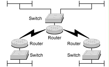
Figure 2: Connection of branches
Remote Access Service
In small and medium-sized networks, routers are often also used for dialling into local networks (LANs). However, dial-in options should not be integrated directly into a LAN, but a dial-in router offering the corresponding security functionality should at least be used in order to protect the LAN against attacks attempted using dial-in accesses.
The following figure shows a possible way to protect a dial-in with the help of a router. The router is operated in the DMZ of a security gateway. Additional security is achieved by an authentication process with the help of a RADIUS server. In this case, the router acts as RADIUS client. Remote users may not authenticate directly at the router, but at the RADIUS server. This way, users can be administered centrally on the RADIUS server.
Strong authentication is achieved by using a one-time password procedure (OTP) in combination with a hardware token or a smart card. RADIUS servers usually support the extension of OTP-based procedures by installing plug-ins or by communicating with an OTP server. Another option of achieving strong authentication includes the integration of the remote access solution into an existing public key infrastructure (PKI). In this case, the RADIUS server must be configured for accessing a directory service. This way, a certificate-based strong encryption can be achieved in combination with a smart card. Additional safeguards are described in modules S 4.4 VPN and S 4.5 LAN connection of an IT system via ISDN.
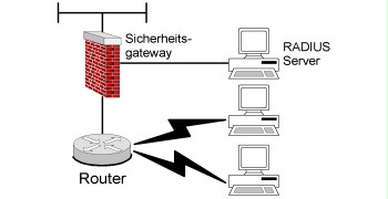
Figure 3: Remote Access Service
VPN
Using Virtual Private Networks (VPNs) constitutes another option of interconnecting sites. A VPN is a secure tunnel routed using existing network infrastructures. This way, the use of VPNs allows secure transmission of confidential information using insecure networks (e.g. the internet). Data traffic between two terminals within a VPN is encrypted. VPN-compatible routers should support strong encryption (e.g. 3DES, AES). Many routers available on the market support the VPN functionality.
IPSec is a standard defined by the IEEE in a series of RFCs and internet drafts. Based on IPSec, VPNs between devices of different manufacturers can be configured. IPSec ensures data confidentiality, data integrity, and authentication between the terminals of the VPN. IPSec is based on the network layer of the OSI reference model. It uses Internet Key Exchange (IKE) in order to execute the protocol algorithm agreement in accordance with the local configuration and to generate the encryption and authentication keys. The so-called "SSL-VPN" is another VPN technology based on a standard, where the data traffic is routed via a connection secured with the help of SSL/TLS.
Along with VPNs based on IPSec and SSL, there are various other technologies, both proprietary and open source. Here, it must be taken into consideration that these are not usually mutually compatible and sometimes only available for certain platforms.
If the components involved allow for integration into an existing PKI, the administration of VPNs (specifically key management) may be significantly facilitated and the scalability may be improved.
A differentiation between a site-to-site VPN and a client-to-site VPN is made. A site-to-site VPN serves for connecting networks. Here, the VPN is limited by correspondingly configured, VPN-compatible routers on both sides. This type of VPNs constitutes an alternative for connecting local networks using wide area transmission networks.
For a client-to-site VPN, a VPN is established between a client and a VPN-compatible router. For this, a manufacturer-specific VPN client software must usually be installed on the client. A client-to-site VPN is to be considered another alternative for remote access to local networks.
The following figure illustrates a VPN architecture by way of example.
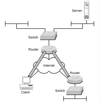
Figure 4: Example of a VPN architecture
Switches
The operational purpose of a switch for forming VLANs is described in safeguard S 2.277 Functional description of a switch. The following figure illustrates a typical switched network:
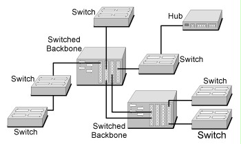
Figure 5: Switched network with backbone and access switches
In the figure, two kinds of switches must be differentiated between. The access switches ,characterised by a large number of ports, ensure the direct connection of the terminal devices. The access switches in turn are connected to central backbone switches.
The backbone switches form the so-called switched backbone. A switched backbone bundles the bandwidth of the connected switches in order to ensure a high throughput rate between the terminal devices. A switched backbone is therefore characterised by high throughput rates. The throughput of a switched backbone depends on several factors to be taken into consideration when procuring devices. The most important factors include the maximum address cache for storing the dynamically learnt MAC addresses, the throughput of the backplane of a backbone switch, as well as the speed of information transfer of the switched backbone.
The switches involved must exchange dynamically learnt switching tables in an architecture similar to the figure in order to be able to efficiently establish the connection between terminal devices connected to different switches. This is performed by using mostly manufacturer-dependent (proprietary) protocols (e.g. Cisco Discovery Protocol - CDP)
In large switched networks, switches are typically cascaded. In practice, this is achieved with the help of the so-called uplink port.
Review questions:
- Has the operational purpose of the existing routers and switches been documented?