
S 5.13 Appropriate use of equipment for network coupling
Initiation responsibility: IT Security Officer, Head of IT
Implementation responsibility: Head of IT, Administrator
Devices used for network coupling such as routers, bridges, and gateways not only connect networks, but can also be used for the physical or logical segmentation of networks. By dividing a large network into subnetworks, it is possible to improve the availability, for example, since an error will only affect a limited section of the network and can be localised quickly. As the number of network stations increases, response times may become unacceptable, and it may be necessary to form subnetworks to distribute the load. The protection of sensitive information is another reason for segmenting networks so that this information is not available on the entire network. To protect an organisation against attackers from the outside, it may make sense to only allow packets to be transferred from secure networks to insecure networks. On the other hand, it may make sense to prohibit the transfer of packets from secure networks to insecure networks in order to protect confidential data.
A segmentation or coupling of networks can be performed on various layers in accordance with the OSI model. Examples of network coupling components include repeaters on the physical layer (layer 1) of the OSI model, bridges on the data link layer (layer 2), routers on the network layer (layer 3), and gateways, which are generally on the application layer (layer 7). The illustration below is intended to aid understanding of the OSI model.
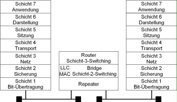
Figure: The OSI/ISO reference model
Connecting one network to another network on a higher layer (layer 3 or higher) of the OSI model allows, for example, the flow of data to be controlled according to the security requirements, and therefore to connect networks requiring protection to insecure networks in a controlled manner.
On the other hand, it may be necessary to separate two networks when each network needs to be protected against access from the other network and vice-versa in order to increase the availability of the network in case of an error or to reduce the network load in the corresponding network segments.
To prevent manipulation, all devices used for network coupling purposes must be configured so that only authorised persons have physical access to the devices.
Repeaters
Repeaters operate on layer 1 of the OSI model and are simple signal amplifiers. Repeaters allow you to extend the maximum cable length of an existing network segment or to connect several different network segments together. In an Ethernet network based on coaxial cables, for example, repeaters can be used to extend the maximum cable length to over 185 m or over 500 m (for thin or thick Ethernet cables, respectively). When using repeaters, the configuration rules for repeaters that restrict the number and layout of the repeaters must be followed.
In the case of twisted-pair cabling, repeaters are often used as central or decentral network nodes for the purpose of linking individual network subscribers. Since several repeaters need to be connected to each other in a single device in this case, these devices are also referred to as multiport repeaters. Multiport repeaters are also frequently referred to as hubs or mini-hubs.
By separating the networks on layer 1 of the OSI model, it is possible to restrict electrical errors in the network to a single segment. This does not apply, though, to errors on higher layers (e.g. when collisions occur too frequently or in the event of a broadcast storm). Some manufacturers today also offer multiport repeaters that evaluate information from layer 2 (but are still not full bridges) and therefore allow the implementation of access restrictions. Such devices can be used to configure access so that only certain network subscribers have access to the network, for example.
Bridges
Networks are connected in Level 2 of the ISO/OSI reference model using bridges. A bridge connects two networks that generally use the same Logical Link Control (LLC) protocol but different Medium Access Control (MAC) protocols. A bridge can be used to connect an Ethernet to a token ring network, for example. Such a bridge is then referred to as a translation bridge or T-bridge.
This results in three important advantages:
- The bridge separates collision domains, which means performance-reducing collisions in CSMA/CD-based networks will not impair the other segments.
- A bridge only forwards data packets to another segment when the destination address of the data packet is located in that segment. As a result of this, data traffic is restricted to the segment actually required, which in turn increases the level of protection against eavesdropping.
- Finally, bridges also increase the data throughput in each segment because data can be transmitted independently on each side of the bridge, and therefore separating the load.
Switches (Ethernet, Token Ring, ATM)
A switch is a variant of a bridge that connects several logical LAN segments (multiport bridge). Switches therefore operate on layer 2 of the OSI model. Some newer products also implement switching functionality on layer 3 of the OSI model, and therefore allow segmentation on layer 3.
An Ethernet switch consists of several bridges that are connected to each other internally in a suitable manner (using a switching matrix, for example).
An Ethernet switch offers the advantages of a bridge for multiple ports (8 to 32 ports per switch are common today), which means that each network subscriber and each segment connected to a switch port forms a separate collision domain and that connections are established based on the actual demand. This allows each segment connected to communicate with all other segments regardless of the amount of traffic or load on the other segment as long as the corresponding segment is not already busy. Switches are particularly useful for load separation and as central coupling components for connecting several subsegments. Very high-performance networks can be formed when a suitable network configuration is selected by cascading switches, i.e. by connecting secondary switches to one central switch.
Ethernet switches that operate according to the IEEE standard for bridges use the store-and-forward technology. With this technology, the entire Ethernet packet from the source port is read in first and then checked for correctness. Only those packets received correctly and in their entirety are forwarded to the destination segment. The transmission delay of such switches is relatively long, but they also guarantee that no bad packets are transmitted to other segments. The use of such store-and-forward switches is advisable in situations where maximum availability and integrity are of greater importance than bandwidth.
In contrast, alternative technologies have been developed that increase the throughput of an Ethernet switch, i.e. they shorten the transmission delay of the data packets they process. To accomplish this, such switches use an on-the-fly technique (also referred to as cut-through switching). On-the-fly techniques do not read in and check the entire packet, but merely evaluate the destination address of the packet and send the entire packet to this address immediately thereafter. On-the-fly switches are therefore up to a maximum of 20 times faster than store-and-forward switches. However, they also transfer bad packets to the other segments, which can then adversely affect the bandwidth, and under some circumstances the availability as well, of the individual segments. On-the-fly switches should therefore be used in networks in which bad packets are rarely transmitted and in which maximum throughput is required. Most manufacturers today offer switches that incorporate both technologies and can be configured accordingly.
Some products now support switching on layer 3 of the OSI model as well. In this case, the network subscribers are no longer distinguished by their MAC address (layer 2 switching), but based on the address on layer 3 (in the TCP/IP protocol stack, this address is the IP address). Layer 3 switching offers additional performance advantages, but in this case, though, the switch must be able to process the protocols used on layer 3 (similarly to a router).
The functionality of switches for ATM or token ring networks is very similar to the functionality of an Ethernet switch, i.e. switches for these protocols allow two network subscribers or network segments to communicate independently of each other. In fact, the basic design of ATM networks makes the use of switches mandatory.
When selecting switches to be used to implement a collapsed backbone, the port density provided by the switches must be taken into account. The need to use switches that are not equipped with the same (high-speed) backplane should be avoided in collapsed backbones (see S 5.2 Selection of an appropriate network topography).
Routers
Routers connect or separate networks on layer 3 of the OSI model. This means that routers cannot provide protocol-transparent operation (like repeaters or bridges, for example), but must be able to process the protocols used in the network layer as well. Routers therefore slow down the data traffic between two connected subnetworks because the routers need to evaluate every packet on layer 3.
Due to their ability to process and implement protocols, routers are used especially for LAN-LAN coupling and to connect LANs to WANs. A router can connect two LANs over an ISDN line, for example. In this case, the LAN protocol is encapsulated unchanged in the WAN protocol and then transmitted. Another example of a protocol that can be used for this purpose is the X.25 protocol. In large networks in which numerous subnetworks are connected by routers, the most important task of a router is selecting the route to take between the subnetworks. There are two basic routing methods available for use:
- Static routing, in which case the route is specified manually.
- Dynamic routing, in which case the route is selected by the router and then continuously updated. There are several algorithms and protocols available for dynamic routing that also guarantee synchronisation of the routers. The best-known protocols are RIP (Routing Information Protocol), OSPF (Open Shortest Path First), and IGRP (Interior Gateway Routing Protocol). Safeguard S 4.82 Secure configuration of active network components also needs to be taken into account when selecting a suitable routing protocol.
Furthermore, filters can also be used to guarantee access control, i.e. to specify which systems can communicate in which direction over the router using which protocols.
Concentrators and hubs
A hub is a component containing one or more active network coupling components that allows these components to communicate with each other over an internal backplane (see also S 5.2 Selection of an appropriate network topology). Hubs that can be equipped with multiple network coupling components when needed are referred to as modular hubs. Accordingly, hubs consisting of only one coupling component that are not designed to be equipped with additional components are referred to as non-modular hubs. If it is possible to connect the backplanes of several hubs to each other, then these hubs are referred to as stackable hubs. When hubs or concentrators are used, some of the cables connected to the end devices form a star topology, and hubs or concentrators are also referred to as star couplers for this reason.
As already mentioned in the section on repeaters, the simplest type of concentrator or hub is a multiport repeater. In contrast, different types of coupling elements can be added to modular hubs, which in turn can operate on different layers (e.g. repeaters, bridges, and routers). The concentration of network coupling components at one single point brings advantages in terms of facilitating administration of the network, although the failure of a central hub will also lead to the failure of the entire network. To avoid such situations, suitable precautionary safeguards should be implemented, for example using redundantly designed network components (see S 6.53 Redundant arrangement of network components).
Gateways
A gateway connects two networks on the application layer (layer 7) of the OSI model. For this reason, a gateway not only performs the task of converting network protocols, but also transports the data in the application level, and if necessary, modifies this data and evaluates it from a security perspective. A typical application for a gateway is to enable communication between systems in a TCP/IP network and an SNA host. In this case, the gateway consists of a combination of hardware and software. However, there are also gateways available that are implemented using software only. An example of such a gateway is a mail gateway, which is able to recognise and convert different mail formats.
Review questions:
- Are suitable network coupling elements selected in accordance with the ISO/OSI reference model, taking the requirements for network segmentation into account?