
S 5.61 Suitable physical segmentation
Initiation responsibility: IT Security Officer, Head of IT
Implementation responsibility: Administrator
Physical segmentation is understood to be the process of forming segments with the help of active and passive network components on layer 1, 2, or 3. A suitable physical segmentation can be used to increase the availability, integrity, and confidentiality. Various network components can be used to perform segmentation (see S 5.13 Appropriate use of equipment for network coupling).
Availability
The performance and the available bandwidth of a network are also considered from the perspective of availability. The availability can be increased when the network is separated on layer 1, 2, or 3 of the OSI model. Separation on layer 1 offers the smallest increase in availability in each segment but the highest throughput between the segments, and separation on layer 3 provides the greatest increase in availability and the lowest throughput between segments.
Segmentation on layer 1 using a repeater increases the availability of the network because electrical errors in one segment cannot affect the other segments any more.
Example: In a network consisting of two Thin Ethernet segments connected to each other by a repeater, the absence of a terminator in one segment will not affect the operation of the other segment.
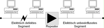
Figure: Electrical separation of segments using a repeater to increase availability
The example also applies to bridges and switches as well as repeaters since bridges and switches also cover layer 1. In addition to providing electrical separation, faulty data packets are isolated to layer 2, and collisions are isolated to a single segment. Furthermore, the load placed on each segment is reduced since data packets only need to be passed between the segments when necessary. In order to process the data traffic flowing between the segments without any long delays, it must be ensured that the bridge or switch used has sufficient capacity (filter rate and transfer rate).
Bridges and switches usually operate on layer 2 of the OSI model. They evaluate the MAC addresses of the systems located in the corresponding segments in order to set up the connection matrix. Some manufacturers also offer switches which operate on layer 3, thus using the IP address, for example, to set up the connection matrix The matrix is generated automatically in both cases, but some models allow manual intervention. Some manufacturers also offer options for setting up the connection matrix manually (using a central tool) at the port level, i.e. at the level in which the cables are actually routed (referred to as port or configuration switching).
In terms of availability, routers operating on layer 3 incorporate the properties of repeaters and bridges while also providing capabilities for evaluating protocols on layer 3. This results in a load separation on a higher level, thus permitting almost full control of network traffic. In particular, broadcasts are not passed between segments (subnetworks) that are separated by a router. For this reason, a broadcast storm in one segment cannot affect the other segments.
Based on the results of a traffic flow analysis performed on the network (see S 2.139 Survey of the existing network environment), it may be necessary to physically segment the network in order to increase the bandwidth or performance to the required extent.
Example: Within a network there are central server systems for file and printing services and for the applications, or provision has been made for such servers. In order to achieve a high level of performance and availability, it might be advisable to have dedicated servers connected to a switch, from where the server systems are linked with the individual workstations (shared or switched mode). If possible, a Fast Ethernet connection should be used for the connection between the servers and the switch.
In general, a switched network should be preferred over a shared network in order to achieve higher performance because in a shared network all subscribers connected to the network need to share the available bandwidth. A switched network, though, offers every subscriber the full bandwidth, at least up to the next active network component. It must be noted in this case, however, that a fully switched network requires structured cabling (star topology) and is relatively costly.
As an alternative, it is possible to use solutions that connect individual network segments in the backbone or in sections with high network loads (e.g. workgroups) using a switch and in which each network segment is designed as a shared media LAN (see Figure 2). In addition, it is always possible to connect individual workstation systems with high performance requirements directly to a switch. While a shared network or a shared segment can be configured using a bus or a star topology, it makes sense to implement them using structured cabling (star topology) for reasons of availability and investment protection (see S 5.2 Selection of an appropriate network topography).
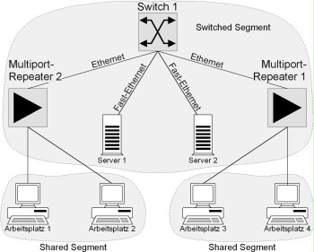
Figure: Example of a network consisting of switched and shared segments. The servers are connected to the switch using Fast Ethernet connections.
Confidentiality
All safeguards that prevent the exchange of data between two segments are suitable for increasing the confidentiality. For this reason, a repeater alone is not suitable for increasing the confidentiality. Some manufacturers offer multiport repeaters that can be configured so that only certain network subscribers are allowed to work in the network over such a repeater. As a result of this, it can be assumed to a certain extent that unauthorised users will not be able to connect to the network. Bridges/switches and routers increase confidentiality because they can block and control the data traffic on layer 2 and layer 3 and can connect or separate segments at the port level in a dedicated manner. It is also possible to restrict access to the network for certain subscribers using the bridges/switches offered by some manufacturers. Routers offer the most comprehensive control capabilities for the components discussed here. With the help of routers, it is not only possible to enable access and select routes to other networks, but also to specify which network clients are allowed to communicate with systems in the other segment. By excluding certain layer 3 protocols, the router can prevent the data related to these protocols from reaching the other segment. This is achieved by defining suitable filter rules in the routers that can be formulated on the protocol layer. When using the TCP/IP protocol stack, for example, it is possible to selectively disable or enable individual TCP and UDP ports for transfer to the other segment. Components operating on higher layers such as application level firewalls are not handled in this section (see S 2.75 Selection of a suitable application-level gateway).
Example: Separating a network with the help of a router and appropriately configured filter rules can prevent the transfer of FTP and TFTP data (ports 20 and 21 and 69 respectively) between the segments and thus prevent this service from being intercepted by the other segment. Likewise, no broadcast data is transmitted between the subnetworks. In addition, the default configuration of the filter must restrict communication to a minimum so that communication is only enabled when needed and for the corresponding services. The use of an IP-based filter should be considered for this purpose.
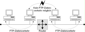
Figure: Example of the separation of subnetworks on layer 3 using a router
Data and network integrity
The integrity of the data up to layer 3 is generally ensured by the network access protocol used, but additional safeguards are required to ensure the network integrity, i.e. to ensure that the current network situation matches the planned physical and logical segmentation of the network. These safeguards must ensure that no unauthorised or misrouted communication connections can be established and that unauthorised access (which would be blocked if the network integrity was intact) to the systems is impossible.
The network integrity is primarily ensured by the following:
- By immediately preventing (or at least detecting) all changes to network components (rearranging components or installing additional unauthorised components, etc.). This is referred to as hardware-based security.
- By preventing (or at least detecting) all changes to the configurations of the network components (e.g. to routing protocols, to the port switching matrix, or to the VLAN allocation). This is referred to as software-based security.
To accomplish this, it is necessary to reject access to the network components with sufficient force (for example using infrastructural safeguards in the distribution room, cabling, etc.) and to design the network management so that unauthorised access to the network components over the network is prevented.
The use of network components alone cannot increase the protection of the integrity of the data on layer 3 (of the application data, for example), but they can make direct attacks on the data integrity more difficult. Network components that prevent data packets from being intercepted and changed can be used for this purpose. Such components include, for example, bridges/switches and routers that are able to divide a network into segments or subnetworks and control, restrict, or configure the data traffic flowing between the segments or subnetworks. The mapping of the logical relationships to the physical configuration plays a key role in this case, especially when using network components that are configured automatically such as bridges and switches. This is the only way to ensure that the data packets in a logical group also actually stay in the same physical segment. With bridges/switches that allow the possible connections to be configured at the port level (port switching), it is also possible to control the connection capabilities on layer 1 manually.
Example: Systems that allow terminals to connect to a network (terminal servers) and systems accessed through the terminal servers must be located in a segment separated from the rest of the network by a bridge. This is the only way to prevent the passwords exchanged between the terminal servers and the systems accessed from being intercepted (and possibly changed) from another segment.
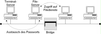
Figure: Separation of segments by a bridge to increase integrity and confidentiality
In addition, the network components selected must provide enough capacity in order to ensure that data packets cannot be lost or corrupted due to the overloading or malfunction of these network components.
Review questions:
- Was physical segmentation considered when designing the local network?