
S 3.302 Routers and switches
Description
Networks play an increasingly important role as parts of the IT infrastructure, since applications are increasingly operated using local area networks or wide area networks. The availability, integrity, and confidentiality of the networks must be ensured and at least meet the requirements of the applications regarding the protection of these three basic values of information security.
A network consists of active and passive network technology. Passive network technology is primarily considered to be the structured cabling system. This also includes patch fields (cable distributors configurable using plug-in panels), protective cabinets, and connection sockets at the workplace. Active network technology includes hubs, bridges, switches, and routers, for example. In state-of-the-art networks, switches today frequently replace hubs and bridges. The failure of one or more components of the active network technology (routers and switches) may lead to the complete shutdown of the entire IT infrastructure. Since these components form the basis and the backbone of the IT infrastructure, routers and switches must be protected against unauthorised accesses and manipulations.
The mode of operation of routers is described in S 2.276 Functional description of a router. Safeguard S 2.277 Functional description of a switch describes the mode of operation of a switch. The most important function-related differences of the active network components illustrated in the following figure are explained briefly.
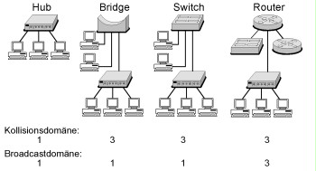
Figure: Hub, Bridge, Switch and Router
Collision domain
A collision domain is an individual segment within the network access procedure CSMA/CD (Carrier Sense Multiple Access with Collision Detection). All devices connected in the same segment are part of this collision domain. If two devices try to send packets into the network at the same time, this is referred to as a collision. Both devices wait for a randomly selected period and then try to send the packet again. This waiting time reduces the efficient bandwidth available to the devices.
Broadcast domai
Broadcast information is not directed to a certain terminal device, but to all "adjacent" terminal devices. Those devices in the network receiving the respective broadcast information of the other devices together form a broadcast domain. Devices consolidated in a broadcast domain do not have to be located in the same collision domain. In this case, the IP protocol is also referred to as an IP subnet. For example, the stations with the IP addresses from 192.168.1.1 to 192.168.1.254 form a broadcast domain in an IP subnet with a subnet mask of 255.255.255.0.
Hub
Hubs work on OSI layer 1 (bit transmission layer). All connected devices are located in the same collision domain and thus in the same broadcast domain. Today, hubs are replaced by access switches (see S 2.277 Functional description of a switch).
Bridge
Bridges connect networks on OSI layer 2 (protection layer) and segment collision domains. Every segment and/or port at a bridge forms its own collision domain. All connected stations are normally part of a broadcast domain. Bridges may also be used in order to connect networks with different topographies (Ethernet, Token Ring, FDDI, etc.) on OSI layer 2 (transparent bridging, translational bridging). Bridges are predominantly used for load balancing in networks. The relief is achieved by a bridge no longer forwarding every data packet as the central transition between two network segments. A bridge has an internal MAC address table showing the connected segments corresponding MAC addresses can be found in. For example, if the bridge is provided a data packet from sub-segment A for a station in sub-segment B, the data packet is forwarded. On the contrary, if the bridge is provided with a data packet from sub-segment A for a station in sub-segment A, this data packet will not be transmitted into sub-segment B. This way, sub-segment B is relieved. Nowadays, bridges are replaced by switches.
Layer-2-Switch
Traditional layer 2 switches connect networks on OSI layer 2. Every switch port forms its own collision domain. Normally, all connected stations are part of a broadcast domain. This means that a layer 2 switch uses the destination MAC address in the MAC header as decision criterion as to which port the incoming data packets are forwarded to. Despite the comparable mode of operation, there are two essential differences from bridges:
- A switch normally connects significantly more sub-segments than a bridge.
- The design of a switch is based on so-called application specific interface circuits (ASICs). Thus, a switch is able to transport data packets from one segment to another segment significantly more quickly than a bridge. Different switching technologies are described in S 2.277 Functional description of a switch.
Occasionally, switches are also referred to as multiport bridges.
Router
Routers work on OSI layer 3 (network layer) and transport data packets based on the destination IP address in the IP header. Every interface on a router constitutes its own broadcast domain and therefore also a collision domain. Routers are not able to connect networks with different topologies. Routers are used in order to segment local networks or to connect local networks via wide area networks. A router identifies a suitable connection between the source system and/or source network and the destination system and/or destination network. In most cases, this is performed by forwarding the data packet to the next router, the so-called next hop. Further information is described in S 2.276 Functional description of a router.
Routers must analyse every IP packet before forwarding. This results in delays and therefore in a lower throughput when compared to "classic" switches.
Layer 3 switch and layer 4 switch
Layer 3 and layer 4 switches are switches additionally offering routing functionality. Layer 2 switches use the destination MAC address in the MAC header of a packet to decide which port data packets are forwarded to. A layer 3 switch handles data packets like a router the first time (destination IP addresses in the IP header). All following data packets of the sender to this recipient are then forwarded on OSI layer 2 (destination MAC address in the MAC header). This way, such a switch can achieve a significantly higher throughput rate when compared to traditional routers.
Another distinction between a router and a layer 3 switch includes the number of ports for connecting individual terminal devices. Normally, a layer 3 switch has significantly more ports.
Differentiation
This module describes the threats and safeguards regarding the use of routers and switches. The differentiation between routers and switches is made more difficult by the introduction of the denominations layer 2 switch, layer 3 switch, or layer 4 switch by different manufacturers. Due to the amalgamation of the functions of routers and switches, the majority of the safeguards described are applicable to both the routers and switches.
A huge selection of different routers and switches from different manufacturers is available on the market. The description of the safeguards and threats in this module is designed as manufacturer-independently as possible.
Along with the comprehensive aspects and the infrastructural safeguards, module S 4.1 Heterogeneous networks must be taken into consideration when using routers and switches. Specifically when integrating the active network components into comprehensive network and system management, module S 4.2 Network and system management is of particular importance. When using a router as packet filter or as dial-in option, modules S 3.301 Security gateway (firewall) and S 4.4 VPN must be taken into consideration additionally.
Along with specifically manufactured devices, different operating systems (for example diverse Unix derivatives, Windows 2000, etc.) also offer routing functions. This means that a router may consist of a corresponding computer with one or more network cards and a default operating system. In smaller local networks , this may be a cost-effective alternative under some circumstances. Along with the security safeguards described in this module, the security safeguards of the operating system used (Unix, Windows 2000, etc.) must be taken into consideration when operating such a router.
Threat scenario
Along with the threats generally applicable to the majority of IT systems, there is a host of specific threats for active network components.
These threats are often based in known vulnerabilities in the protocols used such as TCP, UDP, IP, or ICMP. For examples, routing tables on routers may be modified with the help of vulnerabilities in dynamic routing protocols. Another threat includes the often missing or poor authentication option on active network components.
Active network components are often delivered with an insecure default configuration (see T 4.49 Insecure default settings on routers and switches) that should be checked when commissioning the devices. In order to securely separate subnets with different protection requirements, the use of virtual networks (VLANs) is sometimes suggested. However, a couple of attack methods are known which enable the overcoming of the boundaries between VLANs and accessing of other VLANs in an unauthorised manner (see T 5.115 Overcoming the boundaries between VLANs).
An overview of the threat situation regarding the use of routers and switches can be found in the following:
Organisational Shortcomings
| T 2.1 | Lack of, or insufficient, rules |
| T 2.3 | Lack of, inadequate, incompatible resources |
| T 2.4 | Insufficient monitoring of security safeguards |
| T 2.22 | Lack of or insufficient evaluation of auditing data |
| T 2.27 | Lack of or insufficient documentation |
| T 2.44 | Incompatible active and passive network components |
| T 2.54 | Loss of confidentiality through hidden pieces of data |
| T 2.98 | Incorrect planning and design of the use of routers and switches |
Human Error
| T 3.64 | Incorrect configuration of routers and switches |
| T 3.65 | Incorrect administration of routers and switches |
Technical Failure
| T 4.49 | Insecure default settings on routers and switches |
Deliberate Acts
| T 5.4 | Theft |
| T 5.51 | Abuse of routing protocols |
| T 5.66 | Unauthorised connection of IT systems to a network |
| T 5.112 | Manipulation of ARP tables |
| T 5.113 | MAC spoofing |
| T 5.114 | Misuse of spanning tree |
| T 5.115 | Overcoming the boundaries between VLANs |
Method recommendation
The security safeguards assigned to this module are based on the lifecycle of the active network components. Safeguards categorised in the following cycles are described:
- Planning and design of the use of routers and switches
The use of routers and switches requires careful planning. The functions of routers and switches are described in S 2.276 Functional description of a router and S 2.277 Functional description of a switch. Typical operational scenarios of routers and switches that may be helpful during the planning and design phases are described in S 2.278 Typical operational scenarios in which routers and switches are used. - Definition of a security strategy for routers and switches
Before procuring active network components (see S 2.280 Criteria for the procurement and selection of suitable routers and switches), a security strategy for securely operating the devices must be defined and documented (see S 2.279 Drawing up a security policy for routers and switches). Then, suitable network switching elements may be selected that must then be integrated securely into the existing network infrastructure. In this phase, it is furthermore important to train the administrators in secure administration (see S 3.38 Administrator training on routers and switches). - Configuration and commissioning of routers and switches
When configuring and commissioning routers and switches, a host of important security safeguards must be taken into consideration. Insecure default configurations of network components often constitute a significant security risk. Therefore, the configuration must be checked and adapted during commissioning.
When commissioning routers and switches, the proper configuration of the systems plays a huge role (see S 4.201 Secure basic local configuration of routers and switches and S 4.202 Secure basic network configuration of routers and switches). When using routers, it must furthermore be ensured that the routing protocols are used securely. Depending on the operational purpose, access control lists (ACLs) should be configured on routers (see S 5.111 Configuration of access control lists on routers). Here, but also during normal operations, the system configuration must be documented carefully (see S 2.281 Documentation of the system configuration of routers and switches).
Furthermore, routers are often used for secure dial-in and for establishing virtual private networks (VPNs). When configuring VLANs on switches, a couple of security aspects must be taken into consideration. In summary, S 4.203 Configuration checklist for routers and switches contains a checklist for securely configuring routers and switches. - Secure operation of routers and switches
Information on securely operating routers and switches can be found in S 2.282 Regular checking of routers and switches, S 2.283 Software maintenance on routers and switches, and S 6.91 Data backup and recovery on routers and switches. Logging aspects for routers and switches are described in S 4.205 Logging on routers and switches. Security aspects important in the event of a malfunction are described in S 6.92 Contingency planning for routers and switches. - Security aspects when decommissioning routers and switches
Stored configuration files and log files on routers and switches give away information about the network structure. When decommissioning active network components, the information in S 2.284 Secure withdrawal from operation of routers and switches must be taken into consideration.
In the following, the safeguards to be taken into consideration when using routers and switches are listed:
Planning and design
| S 2.276 | (Z) | Functional description of a router |
| S 2.277 | (Z) | Functional description of a switch |
| S 2.278 | (Z) | Typical operational scenarios in which routers and switches are used |
| S 2.279 | (A) | Drawing up a security policy for routers and switches |
Purchasing
| S 2.280 | (C) | Criteria for the procurement and selection of suitable routers and switches |
Implementation
| S 1.43 | (A) | Secure installation of active network components |
| S 3.38 | (B) | Administrator training on routers and switches |
| S 4.201 | (A) | Secure basic local configuration of routers and switches |
| S 4.202 | (A) | Secure basic network configuration of routers and switches |
| S 4.203 | (A) | Configuration checklist for routers and switches |
| S 5.111 | (C) | Configuration of access control lists on routers |
Operation
| S 2.281 | (A) | Documentation of the system configuration of routers and switches |
| S 2.282 | (A) | Regular checking of routers and switches |
| S 2.283 | (B) | Software maintenance on routers and switches |
| S 4.204 | (C) | Secure administration of routers and switches |
| S 4.205 | (C) | Logging on routers and switches |
| S 4.206 | (C) | Protection of switch ports |
| S 5.112 | (C) | Security aspects of routing protocols |
Disposal
| S 2.284 | (C) | Secure withdrawal from operation of routers and switches |
Contingency Planning
| S 6.91 | (C) | Data backup and recovery on routers and switches |
| S 6.92 | (C) | Contingency planning for routers and switches |